
About:2-Node Thermal
Internal Temperature (2-node) Model - resolve bulk and surface temperature for improved voltage prediction
Overview
The Internal Temperature (2-node) thermal model extends the About:Lumped 0D thermal model by resolving the temperature difference between the interior of a cylindrical cell and its surface. The model predicts the volume-average (bulk) temperature, which governs the electrical response of the cell, together with the temperature of the cooled surface.
The thermal domain of the cell is divided into two nodes: a bulk node at the volume-average temperature of the cell, and a surface node at the temperature of its surface. The two are separated by the internal thermal resistance \(R_\text{int}\), which is a property of the cell and is supplied with the model. The external thermal resistance \(R_\text{ext}\) is a property of the surrounding thermal environment and is defined by the user. Resolving the surface temperature between the two separates the cell-controlled and environment-controlled parts of the thermal domain.
Resolving the bulk and surface temperatures separately, rather than a single lumped temperature, allows the internal temperature of the cell to be estimated. This matters most under high-rate and low-temperature operation, where the cell develops a significant internal-to-surface temperature gradient. Separately resolving the bulk and surface temperatures also allows model calibration against measurable surface temperatures while the bulk temperature is predicted independently; a 0D lumped model does not support this.
The model is included with the Simulink implementation of About:ECM for supported cylindrical form factors.
Technical Description
The model represents the cell as two thermal nodes connected by a single internal thermal resistance (Figure 1).
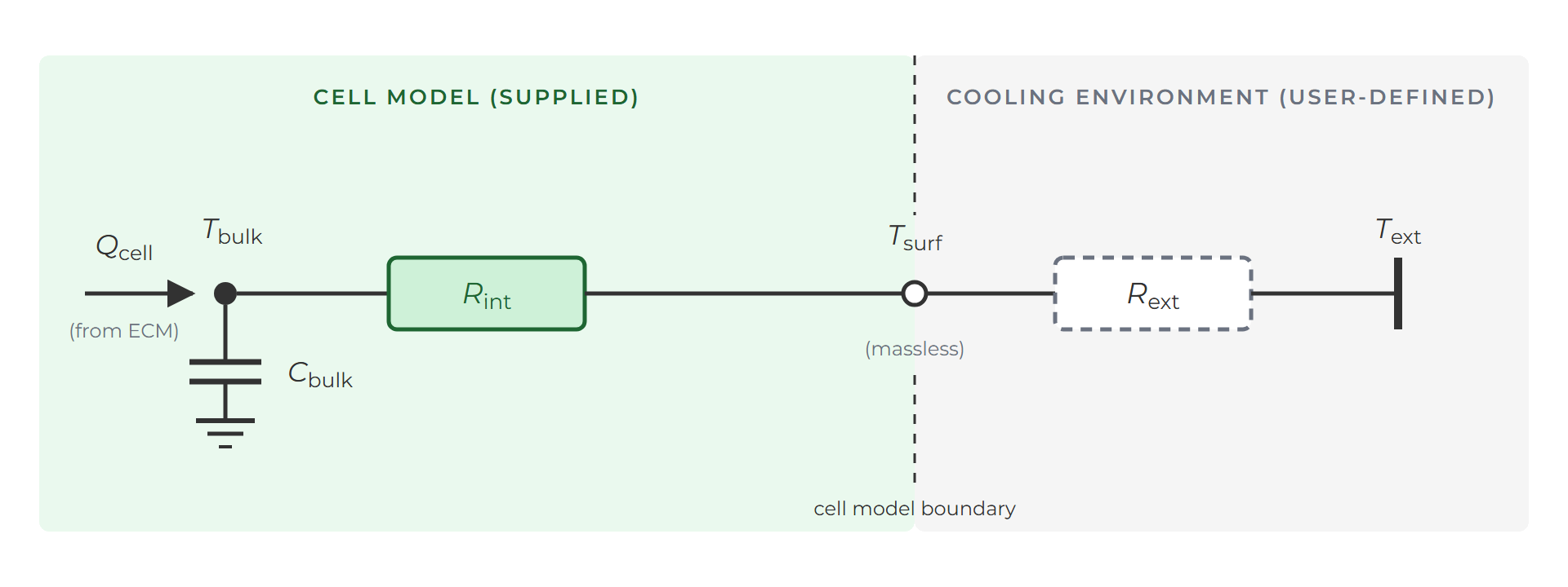
Figure 1: Thermal network of the 2-node model. Components beyond the cell model boundary represent the user-defined cooling environment.
- A bulk node carrying the entire cell thermal mass (total heat capacity \(m C_p\)). Its temperature is the volume-average jelly-roll temperature. It is this temperature that is coupled to the ECM.
- A surface node, which is massless: it has no heat capacity of its own and mediates heat exchange between the bulk and the external cooling boundary.
The bulk node represents a volume average rather than the geometric centre used in core-shell models. \(R_\text{int}\) is defined to reproduce the volume-average-to-surface temperature difference for the selected cooling configuration.
Heat generated by the ECM enters the bulk node, conducts through \(R_\text{int}\) to the surface, and passes across the external thermal resistance \(R_\text{ext}\) to the environment. Because the surface node is massless, the surface temperature responds instantaneously to the heat flow through it. In the limit \(R_\text{int} \to 0\) the two nodes coincide and the model reduces to the 0D lumped model.
Heat leaves the cell through the surfaces defined by the selected cooling configuration (Figure 2): Base-cooled (cell base), Radial surface-cooled (cylindrical surface), or Convection chamber (all exposed surfaces).
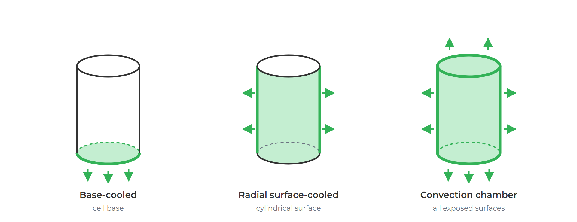
Figure 2: Cooled surfaces for the three supported cooling configurations.
Key features
- Predicts bulk (volume-average) and surface temperature from a single internal thermal resistance.
- Bulk temperature is coupled to the ECM; surface temperature is provided as an output.
- \(R_\text{int}\) is computed by the model from the selected form factor, can material, cooling configuration, and jelly-roll conductivities. No cell-specific thermal parameterisation is required.
- Reuses the cell mass and specific heat capacity supplied in the ECM parameter set.
- Selectable alongside the default Lumped (0D) thermal model.
Key applications
- Thermal design and cooling system sizing where the internal temperature, rather than the surface temperature, sets the limit.
- Definition of BMS thermal limits, derating strategies and safety thresholds from a predicted internal temperature.
- Internal temperature estimation where only surface temperature is measurable.
- Comparison of cooling strategies (base, surface, convection).
- Comparison of cell thermal properties (form factor, can material, jelly-roll thermal conductivity).